starting with PCBs
-
During this class we explore the following topics:
-
this week we started to learn a little bit more about the components of an electronic circuit and how to get familiar with the Eagle software, to design our own PCB, printed circuit board.
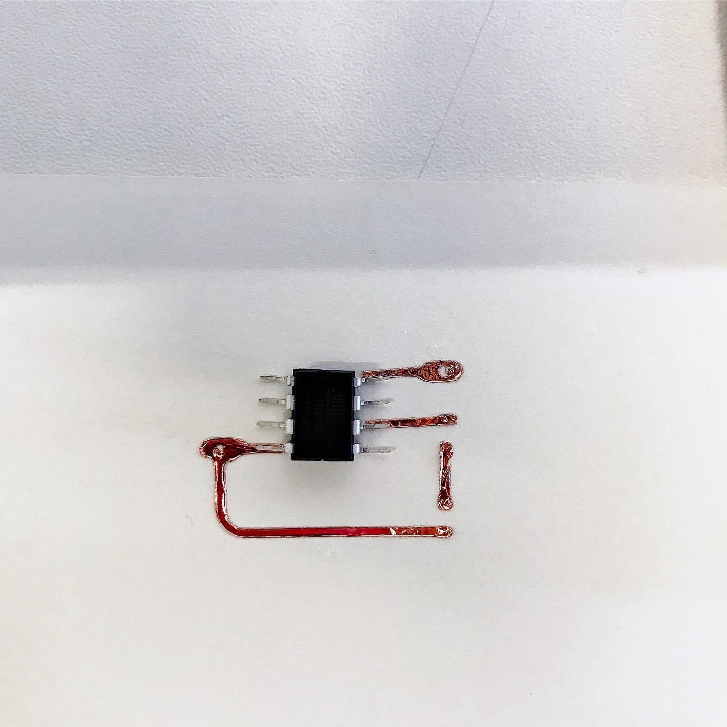
We started to design a small board, using the attiny85DIP, a microcontroller with legs, better known as a through-hole component.
After understanding the requirements of our board and installing the libraries we have finished our PCB schematic.
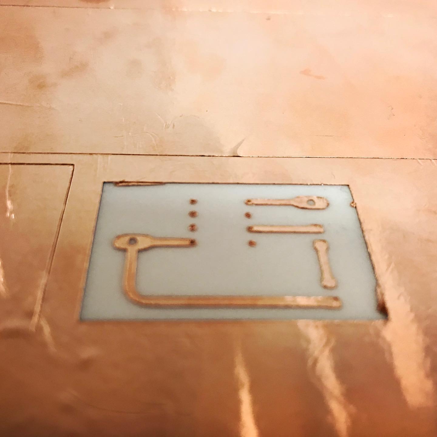
then we proceeded to make the board layout in the board visualization. by making a polygon we solved the export problem and then converted this image from PNG format into vectors in the Sillhouette studio program. We wanted to test the cutting machine to make our copper tape board, to convert the image we used the TRACE command by selecting the image in the size of the drawn polygon, in the future the polygon can be thinner to make the trace function more accurate. After that we scale the image using the TRANSFORM - SCALE function so that it has the same size as the polygon. Setup of the machine: we stuck the copper tape with double-sided tape on the cutter's matte, and proceeded to do the cutting tests. Finally we used pressure 8 and speed 1 to make the most appropriate cuts. Attention: it is important that the cutter is new or has a little distance between the matte and the matte: ca. 4 positions. Then we proceed to cut and transfer the material to the final material, in this case paper. you can see in detail mor information under the projects Wikifactory embedded Systems
Assigment:
1.
finalise your own electronic circuit in the Eagle software, this will add an extra pin for a parallel circuit with at least 2 LEDs.
One of them will have to be placed on one of the PWN pins.
You can add a buzzer or a button.
You will need to cut out your board, using a plotter cutter.
SUPER IMPORTANT !!!! Finally you will document this process on wikifactory.
have a funny week
Adriana Cabrera
recap